The last half-page of the history of Criggion Radio Station was written the weekend of August17, 2003, when the three stayed masts were brought down by explosives. The rest of the page was completed in two bites when one of the Eiffel style towers was demolished in the same way on 19 August with the remaining two being felled similarly on 27 August.

The 25 short wave transmitters and their associated aerials disappeared from the scene in the early 1970s and the VLF (very low frequency) and the three LF (low frequency - about 100kHz) transmitters were hastily dismantled and scrapped when their services were closed down at the end of March, 2003. Now it has been the turn of the supporting towers of the VLF and LF aerials
In the Beginning
But let us start at the beginning. In all probability I have had the longest association with the station than anyone still living apart, possibly, than one Headquarter's officer who helped in seeking out the site in the first place and subsequently was involved with the installation of the external plant. (He died in autumn 2004) The plans were made in 1940 and as Chairman of the P.O. Engineering Union, Radio Branch, based at Rugby Radio Station at the time, The Secretary and I were privileged to see the architect's drawings of what was proposed, and to comment on the provision of staff facilities. That was in the days, even in wartime, in the Post Office and the Civil Service generally, that enlightened consultation with the staff, via the Whitley procedure, was the order of the day, rather than the confrontation that is more the norm currently. The buildings, were to consist of two HF (High frequency or short-wave) stations, an LF (low frequency) station and a VLF (very low frequency) station, all robustly built with thick walls and ceilings to resist possible bombing attacks and with the additional defence of being dispersed on the site.

The site was chosen primarily for a very low frequency (VLF) transmitter to serve as a reserve for Rugby should it succumb to enemy action. Steel was in short supply and it was envisaged that it would be economical in money and resources if a suitable hill were available to support a large aerial. Such a site needed to be reasonably level, close to a source of water for cooling of the thermionic valves and away from any largely inhabited area. Such a site was found at the small hamlet of Criggion in Montgomeryshire about twelve miles south of Oswestry in Shropshire.
A valley running roughly NE-SW is bounded on the one side by the Breidden Hill, about a 1000 ft. above the valley floor, and about half a mile away runs the river Severn. The birth pains were not easy. The valley is good farming land and objections were raised by the Wartime Agricultural Executive Committee. Their fears were assuaged when it was pointed out that agriculture and radio could co-exist but another objection came from the company quarrying the Hill who thought that they might lose staff if the station offered better employment. Neither objection prevailed in view of the importance of the station that was planned and the buildings went up apace in 1941.

By July of 1942 two HF transmitters were working in an environment more like a builder's yard than a radio station. One transmitter was a Standard Telephones and Cables, type CS3B, and the other was a Marconi type SWB8. When I joined the staff in September '42 the buildings were incomplete and the two transmitters were separated from building operations by a large tarpaulin hung from the ceiling. Messing arrangements were primitive, with visiting field-mice climbing the tarpaulin to share our sandwiches. Toilet arrangements comprised two Elsans in the barn outside. The permanent power system had not been completed and the two transmitters and our lighting were supplied by one of two searchlight generators temporarily cabled in, the other being used for stand-by. Needless to say everything became covered with dust from the building operations and ultimately the bearings on the cooling fan for the CS3B transmitter's heat exchanger failed and portable blowers and vacuum cleaners had to be tied in situ to keep the transmitter on the air until its maintenance shut-down.
The Three Towers
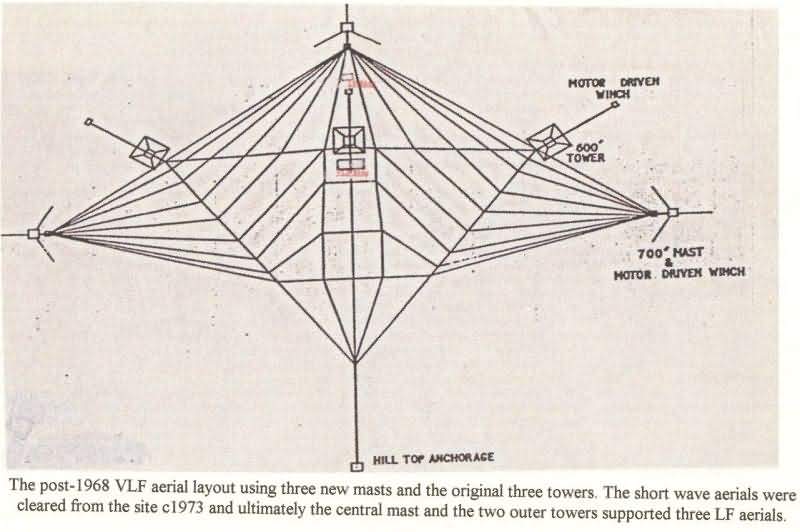
The three towers, of Eiffel shape, were initially intended for the naval station at Trincomalee, Ceylon, but were diverted to Criggion to support the VLF aerial in conjunction with two fixed anchorages on the hill. The site of the station is comprised of a thick bed of alluvium of considerable depth which settled after the last glacial epoch. Test drillings down to 100ft. did not touch bedrock, which is surprising considering the nearness of Breidden Hill which is virtually solid stone. Even nearer to the hill, when test drillings were taken years later for one of the stayed masts a bed of peat was passed through at about 12 feet down. Consequently the foundations of each tower were piled into the ground at each corner, with raking piles extending outwards to give stability. That this was a success was demonstrated by a portable water level device, one chamber of which could be set on a reference slab, and another on each mast footing in turn. Movement has been less than a centimetre.
When the additional stayed masts were erected in 1967/68, for a VLF larger aerial system, their bases were supported on massive reinforced concrete blocks about 30ft. cube and the stays were made off to equally large gravity blocks. At the same time as these additional masts were installed the two hill-top anchorages were replaced by a single winch. Beneath the plan of the original VLF and LF aerials a mesh of wires is buried in the ground to a depth of approximately 9 inches to form the earth system of all the transmitters at that end of the site. That is why only grazing of animals has been allowed on the site with a ban on ploughing.

Mind you, there were times when the River Severn burst its banks, and the site looked like a large lake but, due to foresight, all the buildings had been built up sufficiently to successfully clear the highest floods - just! During the first severe flooding of the site which happened very suddenly during daytime and must have been about '43/44, our boss, the late Harold Woodhead, persuaded the Air Force to drop a dingy to get people away from the site, although most preferred the relative safety of tractor and trailer in fast flowing waters. Some enterprising staff, the late Tim Trotter, as Captain, even improvised a raft from an upturned table between two telegraph poles for inter-building transport. Later, after much persuasion directed to Headquarters, we were provided with our own DUKW vehicle and an amphibious jeep for such occasions. The DUKW was also used for rescuing cows and sheep from the low lying local farms, which if after their use the drivers had not hosed it out, resulted in some choice words from our staff. Happy days and great fun!

The VLF transmitter took over the Rugby traffic in 1943 on a frequency of 16 kHz when that station was destroyed by a fire not related to enemy action. Fortunately the building of GBZ was almost completed and was taking traffic within three days. When it took its own traffic after Rugby's restoration, it used frequencies of 15.2kHZ and 15.4kHz in that order. The valves were cooled with distilled water (and not deionised water as was the later replacement transmitter) which was transported in a large tank by tractor and trailer from one of the HF buildings where we had a distillation plant. This apparatus resulted in a minor contretemps when we were visited, on another matter, by a rather officious Excise Officer. He read us the "riot act" on the need to be licensed for the still but he made a hasty embarrassed exit when he realised that as a Government Department we were "bomb-proof". The riverside pump-house was built concurrently with the HF buildings as river water was circulated through heat-exchangers to cool the distilled water flowing through the valves of the short wave transmitters. Surprisingly, when the Water Resources Act came into force in 1963 we were charged an Abstraction Fee in spite of the fact that we put back what we took out, minus a gallon or two by wastage, even if it was at a slightly higher temperature.
Parts from Rugby
Originally Rugby had been provided with five RF power panels but normally only three were used. One of the remainder was complete but the other had been cannibalised for use as a test bed for other types of valves but fortunately its original parts had been retained. It was these two that were dismantled and rebuilt at Criggion.
Each had eighteen 10kW valves in parallel with the two units being paralleled together. These were driven by two similar water-cooled 10kW valves in parallel which in turn were driven by an air-cooled "football" valve in the 2kW stage. The final frequency was provided by a tandem arrangement of two regenerative dividers (a divide by 2 followed by a divide by 3) from a crystal oscillator working around 100kHz. These devices had been provided by the Dollis Hill Research Station. The output drove two tuned amplifiers using receiving type valves followed by a PZ1-75 valve which, in turn, drove the 2kW amplifier. These earlier stages were later replaced by a Vortexion (trademark) 100watt audio amplifier, thereby cutting out three tuned circuits which provided, some improvement in the keyed wave shape.
The 2kW and the 20kW amplifiers, followed by the two power panels, each comprising 18 valves in parallel, were all un-neutralised triodes and that fact coupled with the valve grids' negative resistance characteristic was a formula for instability. It was not helped by the common grid bias and low power HT supplies being provided from rectifiers which had a much higher internal resistances than the generator sets which were used on the equipments when they were installed at Rugby. However, work in the late '40s provided a solution which was not difficult. A resistive grid load on the final stages to compensate for the negative grid current, plus a very large adjustable inductance between anode and grid (suitably blocked for DC) of the 20kW stage to neutralise its anode-grid capacitance, and separate grid bias supplies for each amplifier, gave the answer.

The VLF aerial lead-out insulator was unique. Whereas Rugby managed with a plate glass window until well after its final rebuild, The Criggion insulator, as did the VLF building itself, needed to be as near literally bomb-proof as technically possible. To that end a porcelain insulator was modelled in an electrolytic tank so that the material followed equipotential lines of stress thereby enabling its losses to be as small as possible. For mechanical protection it took the form of a convex bowl in the inside wall of the coil room. To further control and contain the potential stress away from the fabric of the building, since the lead-out voltage was of the order of 230kV, a copper shield surrounded the insulator on the inside of the building and was connected through the wall by screening wires connected to the outer guard ring and weather cowl. Not infrequently, and usually after a shut down or a non-keying period, the lead-out would flash over inside the insulator and a dead bird which had been sheltering in it would fall to the ground. Of later years, sometime after the 1968 rebuild, a bushing type insulator, for some reason, has replaced the original fitment.
Hair Raising Experiences

Since the aerial was much smaller than that at Rugby, and because the operating frequency was lower, not only was the aerial voltage much higher, but the ATI (aerial tuning inductance) coils were wound on bigger diameter spiders to achieve the necessary larger inductance. The walls of the coil room were covered with a copper wire screen to reduce losses in the building and its reinforcing metal because of the quite intense field in the room. One could stand inside, (on the correct side of the safety door) and emulate the Statue of Liberty with a neon bulb or a fluorescent tube in one's hand for it to light up brilliantly. No wonder I and most of my equally aging colleagues are sceptical about the dangers of electro-magnetic radiation!
Each final amplifier had its own mercury vapour rectifier, utilising six GU8 valves, in a three-phase full wave circuit, but the commutation of their output currents, of about 20-30 amps each, reflected back on the mains and telegraphists in the railway station at Oswestry, some fifteen miles distant, could read our traffic from the mains hum. This problem was solved by upgrading the power line from the sub-station on the Oswestry- Newtown System from 11kV to 33kV with our own transformer to feed the station's 11 kV ring-main. In the later re-build of 1967/69 the two power panels each with their 18 valves were replaced by three amplifiers each with a single vapour cooled triode valve; the aerial was made more extensive, by being supported on three additional guyed 700ft masts, thereby reducing the size of the aerial tuning inductance which was achieved by paralleling the "spiders".
The driver stages in the new transmitter comprised a 5kW valve amplifier originally, for each main amplifier which were subsequently replaced by solid-state amplifiers. The rebuild was a copy of the Rugby, GBR, transmitter which had been refurbished earlier in the '60s. Frequency stability, on which several of the sophisticated modes of transmission depend, was provided by a basic Rubidium (or Caesium) oscillator controlling a frequency synthesiser. These improvements enabled the aerial current to be increased from about 400 amps. to about 700 amps.
Of the LF sets, only one was a standard commercial product and that was a Marconi 40kW transmitter with several unusual features. It used a pair of normal air cooled glass/metal neutralised triode valves connected in parallel for the output stage, which was driven by 4 - 813 valves in parallel. Its final tank circuit comprised a pair of paralleled, oppositely wound, units, assembled close together, to reduce the local field and the link coupling coil was provided with a specific value of capacitor in parallel to make it into a low-pass filter for reducing harmonics. The ATI was a similar astatic pair of coils.
The other LF transmitter was a Naval type 22C which was installed by naval personnel. It used silica valves in the power stages and, because similar hard diode valve HT rectifiers were used, which had bad regulation; additional silica envelope triode valves were used as an absorber load on the HT line, conducting alternately with the power valves, in order to preserve the keyed waveshape. Improved regulation of the HT line was achieved by installing a three-phase full wave mercury vapour rectifier, which enabled the absorber valves to be dispensed with.
Surprisingly, many years after the war, we were dunned by Admiralty accountants for naval stores that were provided during its installation. These papers were imaginatively put back into the bureaucratic chain, usually by re-directing to a telephone manager somewhere, miles away, to be lost for ever!
The replacements for these transmitters, in the late 1970s, early 1980s. were of a more recent commercial design but that description is relative. They were second hand transmitters which became available when the Navy closed down its New Waltham station but, first, they were refurbished by PO staff.
Originally all the PO HF transmitters were designed to provide modulated carrier DSB (double sideband) signals, the audio signal modulating the suppresser grid of one of the early pentode amplifiers. This situation persisted until shortly after the end of the war. The surge in post-war traffic, plus the need to provide many circuits for the Cape-Town Olympic Games, spurred on the conversion of all but two of the HF sets to ISB(independent sideband) working, with in some cases, two circuits on each sideband or audio circuits on one sideband and a multi-channel telegraphy system on the other. It should be mentioned, too, that the original SWB8 transmitter was replaced in 1943/4 by a ST&C CS5B transmitter and two CS3B units were provided in the other HF building. These ST&C transmitters all had their own integral water cooling systems.
Towards the end of the European War a Western Electric 2kW SSB transmitter was installed in each HF building for Army traffic. Later, the P.O. built additional purpose designed SSB transmitters (as distinct from the conversions of the earlier transmitters), two in each of the HF buildings. To cope with the ever increasing traffic two air-cooled 8kW transmitters, with motorised wave-change switching; were built by the P.O. plus two ST&C type DS12, 4kW transmitters, were installed in one of the HF buildings. Directions of transmission to distant destinations were limited to within the arc covered by the Breidden Hill and its near neighbours but the more distant hills were no impediment since they subtended lower angles to the site than the radiation from the beam aerials. Most of the HF aerials post-war were rhombic patterns. .
The Criggion Christmas 'Run'
Mention of the war brings to mind that Criggion was in the midst of an agricultural area that did not seem to know that food rationing existed elsewhere in the country. Eggs and butter and the odd bit of bacon or chicken were not impossible to come by. One visiting engineer from London, of senior rank, invariably visited the station carrying an empty suitcase. On his return it was hard to lift into the train. On another occasion, one Christmas, a large enclosed van was returning to London when it was stopped in a queue of vehicles by police checking on Xmas-tree poachers. Shining his lamp on the side of the van, and seeing the Royal Cipher and the PO Title, he passed it on. Had it been opened it would have been found stocked to the roof with farm produce and to be sure heads would have rolled at high level in the Post-Office.
Around the world
Until the Atlantic cable came along, Criggion carried all fourteen circuits to the USA four channels on three transmitters with two broadcast quality circuits on the fourth. Also, due to political animosity with India a land-line connection was not possible between Pakistan and what became Bangladesh, so their traffic came into London from one and out again, via Criggion, to the other. It was on the Indian circuit that Lincompex was first tried, it being a system to control levels to overcome the variations in the radio path. Regrettably it came too late to avoid the demise of HF. Also shortly after the completion of the HF turnkey installation of 28 Marconi HS51 transmitters at Rugby, one was installed at Criggion and was used on the Maritime Telephony service.
But "Sic transit gloria" when cables and satellites came on the scene the HF systems closed down one by one. Later in the first year of the Atlantic cable, in the October if memory is correct, the link at the Canadian end broke down. We were away with all our transatlantic transmitters within the hour - it was about five hours later when the Americans came up. Such was the efficiency of their privatised system!
Pumping out the Valves
Each HF building had a 120kW demountable valve amplifier working on traffic but only one of the two intended 250kw amplifiers was ever completed. It provided several problems mainly due to the high input capacitance and low input resistance of the valves and the need to match that impedance to the driver stage slightly remote from it. The difficulties were overcome but the completion of the first amplifier coincided with a policy decision to scrap all demountable valves. The reasons were two-fold; slow delivery from the manufacturers of replaceable parts and damage to the optically flat seals at the break-joint because staff hadn't been adequately trained. This meant frequent difficulties in getting the valves down to vacuum resulting in the pumping equipment running continuously. Under good conditions it was possible to replace a filament and/or grid electrode within an eight-hour shift. If problems were encountered with the sealing it could take days!
The original stand-by generator comprised a 1500HP English Electric, Fullagar, opposed piston, diesel engine driving a 1000kW alternator. The diesel engine had six cylinders arranged in three pairs with the upper piston in each cylinder cross connected to the lower piston in its partner of the pair of cylinders. The upper cross- heads, to which the bars joining the opposing pistons were connected, worked in boxes above the cylinders forming scavenge pumps to clear the cylinders of exhaust gases after each stroke. The bottom crossheads were connected to the con-rods driving the crankshaft. The alternator supplied the whole of the station and it could be synchronised with the mains to avoid a second shut-down on restoration of the public supply. Such was its size that lubricating oil had to be circulated to "float" the crankshaft before start up. Also, compressed air starting was provided on only two cylinders so that at shut down the engine had to be barred around by means of a large crowbar and teeth on the flywheel to the starting position. These two features meant that there was a delay of anything from five to ten minutes before the emergency power could be connected to the station ring-main at 11kV. This did not meet the requirements when the VLF station was rebuilt in 1968 and consequently a beautiful machine with only about a 1000hrs running life was cut up for scrap.
Striking Oil !
Two events remain in memory about this engine. After the initial run up the lubricating oil circulation was adjusted on a by-pass valve which was operated by a hand-wheel on a screw thread. What I didn't know was that the thread didn't have a stop on it and one day it came off in my hand. I had seen pictures of oil-gushers in the cinema but this was its equal - a stream of warm lubricating oil hit the ceiling and descended onto my head soaking my clothes to the skin.
Another occasion when we were returning the supply to the mains the remote switch, operated over a land-line link and which connected the alternator to the ring main bus-bars in the distant sub-station about a quarter of a mile away, would not open. The only recourse was for someone to visit the distant building and to ensure by telephone that the alternator was off-load and then lower the high-voltage switch from the bus-bars. Fortunately, this worked with only a little sparking as the switch came away.
The Omega Navigation System
One thing of interest is that there was a lull in VLF traffic towards the end of the '50s and GBZ was shut down. The opportunity was taken by the American Naval Electronics Laboratory from San Diego to use the aerial for the initial tests of the Omega Navigation System . They arrived one Saturday evening, unannounced, with a large trailer which had great difficulty getting on to the site. The trailer housed a 250kW air-cooled transmitter and additional aerial loading coils were set up in a plastic dome to tune the system to 10.2kHZ. The RF connection from the dome into the building, to connect with the normal ATI was taken through a polystyrene panel replacing the top light of a doorway. It quickly flashed over and burnt up but a replacement lead through insulator was made from a couple of plastic buckets from Woolworth's, giving a longer leakage path, and that lasted throughout the tests.
The Omega system depended on the Criggion and Haiku (Honolulu) transmitters being slaved on the Boulder (USA) transmitter and to that end a remote receiver was set up in Brogyntyn Hall, some 12 miles distant, (the seat of Lord Harlech), but then occupied by the Lines Branch of the PO.
The transmissions comprised emissions of carrier frequency in individual short sequential time slots which enabled the receiver to pick up the master signal without local interference but obviously the whole link comprising the landline and the radio path from the master station had to be corrected for time delay. In addition the siting of the station had to be determined with some accuracy and this was done by the Naval Hydrographers Department. A later improvement to the system incorporated the sequential use of a second frequency of 13.6kHz (four thirds of 10.2 kHz) interleaved with the original frequency to reduce the anomalies in positional determination.
The Omega System depended on the remote vehicle comparing the time delays in the signals from the master and slave stations to determine its position. Because of subsequent requirements the European station was built elsewhere and Criggion started again to take its own traffic.
Sixty-one Happy Years
As we said at the beginning, the HF services at Criggion finished in about 1971/2 and all the transmitters were scrapped. The VLF and LF services continued until March 2003. Then 61 years of a very happy station was consigned to oblivion. Criggion always was a happy station. Nurtured in wartime a camaraderie grew up amongst the staff that could not be compared with, nor matched at, the other PO radio stations.

The staff settled into the nearby communities and became renowned in the local towns for their carnival floats in summer and during winter their home-produced pantomimes which earned money for local charities. The carnival floats were always replete with firework-bangers, soap bubbles and water jets to spray the onlookers. For the pantomimes we were fortunate in having on the staff the late Eric Mortimore, who as a baritone had won prizes at the Llangollen Eisteddfod and also at the Southport Festival. His singing gave a professional touch to the activities. The scripts were produced by another member of the staff, Dick Hearsey, and were certainly of a professional standard.
Only Memories to Survive?
It might be pertinent here to mention that Criggion along with Rugby, as the two PO/BT VLF stations, and with Leafield and Ongar their LF/HF transmitting stations; together with Baldock and Bearley, as their counterpart receiving stations, nothing will remain to indicate a total period of over 75 years of radio history. We have mills, steam engines, railways and their associated buildings to advertise our industrial heritage. These radio stations are as much a part of our history and heritage. Some part of these stations should be preserved before it is too late. Most of the buildings were purpose built for the technology of their times, and in the case of Criggion additionally for war-time conditions; and they housed equipments which were at the forefront of the technology of their respective eras. Signals from Criggion were sent to the naval ships engaged in the Bismarck action and helped to sink, it, resulting in a complimentary letter being received from the Admiral of the Fleet. Criggion, too, has now been "sunk"! With the exception of Rugby -so far- all have gone because no-one, not even those responsible for preserving our heritage have been interested! Sweden has retained in working order its alternator station at Grimeton and its broadcaster at Motala. Was it impossible for Great Britain to retain a little of our radio past?


